


一、Product Summary
Dear users, thank you for using our electromechanical separation heat meter. Please read this instruction manual carefully before using it, so that you can easily use our products.
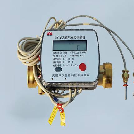
This product belongs to an intelligent heat meter. Its function is to calculate the heat consumed by the user by measuring the flow rate of hot water flowing through the user and the temperature difference between inlet and return water. This heat value will be used as an important reference basis for heating charges to participate in the accounting of heating costs. It is composed of flow sensor, paired temperature sensor and calculator, and its structure is simple, compact and reliable.
二、Working Principle
A pair of temperature 1 sensors are respectively mounted on an upward pipe and a downward pipe passing through a heat-carrying fluid, The flowmeter is installed on the fluid inlet or return line (the flowmeter is installed in different positions, The final measurement results are also different). The flowmeter sends out pulse signals proportional to the flow rate, a pair of temperature sensors give analog signals indicating the temperature level, and the totalizer collects signals from the flow rate and temperature sensors and calculates the heat obtained by the heat exchange system by using the calculation formula.
三、Function List
|
Serial Number |
Functions |
Comments |
|
1 |
Metering function |
Accumulated flow of real-time Hall counter |
|
2 |
Water metering data history storage local |
1. For the latest 90 days, the measurement data is stored every hour 2. The latest 180 days, the measurement data is stored every day 3. Monthly storage of measurement data in the latest year |
|
3 |
Power supply |
1. Battery powered 2. External power supply |
|
4 |
Main battery capacity level indication |
The suffix of that current battery capacity level is report to the server in each metering data message uplink report |
|
5 |
LED indication |
Communication events; Screen Cutting Event |
|
6 |
Manual triggering (triggering varies according to different models) |
Button triggers an escalation event Magnet triggers report event Trigger 1 second switch screen Trigger 2 seconds to report data Trigger more than 9 seconds to restart the device |
|
7 |
Wireless technology |
Lorawan/NB/GPRS |
|
8 |
External Interface |
RS485/Mbus |
|
9 |
Periodic reporting |
1 The default period is 24 hours Latest cumulative measurement data Water meter status: valve status/power supply Battery Capacity Level Downlink Signal Strength Indication |
|
10 |
Timed reporting |
1 Fixed time (for example, 23:00, also configurable) triggers metering data reports every day, and the message payload is the same as the periodic report Latest cumulative measurement data Water meter status: valve status/power supply Battery Capacity Level 5LoRaWAN Downlink Signal Strength Indication RSSI/SNR |
|
11 |
Alarm Message Uplink Report |
Battery Capacity Low Level Alarm Backup Battery Switch Alarm Valve fault alarm |
|
12 |
Screen digital display |
1 Display Content: Current Reading, Electricity Quantity, Balance, Valve Status (Default on, Because Cold Water Meter Has No Valve) 2 Display mode: normally bright (low power consumption screen) |
|
13 |
Mode of transport |
In the transportation mode, log is closed, communication is closed, pulse is not metered, and the operation with minimum power consumption is maintained |
|
14 |
Antenna (Nb/Lorawan/GPRS) |
Built-in antenna (spring/soft antenna) External antenna (chuck antenna) |
|
15 |
Infrared Configuration (Optional, Default None) |
Infrared Setting/Read Table Parameters Infrared Update Program |
|
16 |
Communication mode |
Supported Band |
|
|
M66 (GPRS Communications) |
850/900/1800/1900MHz |
|
|
BC26 (NB Communications) |
B1/B2/B3/B4/B5/B8/B12/B13/B17/B18/B19/B20/B25/B26/B28/B66 |
|
|
BC35G (NB Communications) |
B1 @ H-FDD: 2100 MHz B3 @ H-FDD: 1800 MHz B8 @ H-FDD: 900 MHz B5 @ H-FDD: 850 MHz B20 @ H-FDD: 800 MHz B28 @ H-FDD: 700 MHz |
|
|
BG96 (NB/GPRS/CATM Communications) |
Cat M1/Cat NB1: LTE FDD: B1/B2/B3/B4/B5/B8/B12/B13/B18/ B19/B20/B26/B28 LTE TDD: B39 (For Cat M1 Only) EGPRS: 850/900/1800/1900MHz BG96-M Cat M1: LTE FDD: B1/B2/B3/B4/B5/B8/B12/B13/B18/ B19/B20/B26/B28 LTE TDD: B39 |
|
|
BC66 (NB Communications) |
B1/B2/B3/B4/B5/B8/B12/B13/B17/B18/B19/B20/ B25/B26*/B28/B66 |
|
|
Lorawan Newsletter |
CLASSA, CLASSB and CLASSC modes are supported, and the supported frequency bands are shown in the attachment |
|
|
RS485 communication |
Four lines: red +, black-, yellow A, blue B |
四、Performance characteristics
1. This product uses a high-precision time measuring core to ensure high accuracy and stability of measurement
2. It is equipped with Hall flow sensor, and the liquid flowing through the meter is measured by pulse inside the meter, which will not produce any mechanical wear and has lower maintenance cost
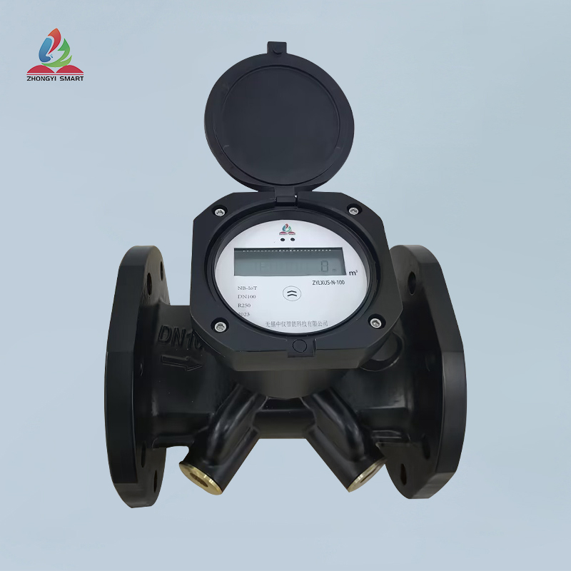
3. It can be installed horizontally or vertically. During installation, it can be installed on the water inlet pipe or return pipe according to different needs of users (the installation position needs to be selected in advance, and the default is water inlet installation)
4. M-BUS, RS485, GPRS, NBIOT and LORAWAN modules can be added according to different needs of users to realize remote automatic meter reading function, which is convenient for centralized management (pre-selected)
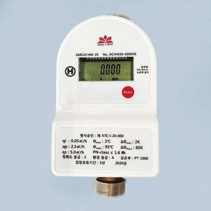
五、Technical Parameters
1. Technical parameters
|
Nominal diameter DN (MM) |
20 |
25 |
|
Minimum flow (m3/h) |
0.05 |
0.07 |
|
Common flow (m3/h) |
2.5 |
3.5 |
|
Maximum flow (m3/h) |
5 |
7 |
|
Maximum water quantity count m3 |
99999.999 |
|
|
Max. Heat reading MW. H |
99999.999 |
|
|
Accuracy level |
Level 2 |
|
|
Pressure loss |
< 25Kpa (under normal flow) |
|
|
Maximum working pressure |
1.6 MPa |
|
|
Heat consumption calculation |
< = 1.0 K |
|
|
Temperature Range |
+30 ~ 90 degrees Celsius |
|
|
Temperature difference range |
3K ~ 60K |
|
|
Temperature resolution |
0.01 degrees Celsius |
|
|
Ambient Temperature |
Class A +5 ~ 55 degrees Celsius |
|
|
Battery operating time |
10 years (section 2) |
|
|
Installation Method |
Horizontal or vertical installation |
|
|
Heat carrier |
H2O |
|
|
Temperature sensor |
PT1000 platinum resistor |
|
|
Display Number of Digits |
8 bits |
|
|
Valve Type |
Ball valve |
|
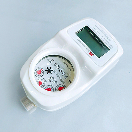
2. Display Description
Non-verification status display:
|
Show Content |
Content Explanation |
Unit |
Display Accuracy |
Comments |
|
Heat |
Accumulated heat |
MWH |
3 |
|
|
Flow |
Cumulative flow |
M3 |
3 |
|
|
T in |
Inlet water temperature |
Celsius |
0.01 |
|
|
T Out |
Outlet water temperature |
Celsius |
0.01 |
|
|
Flow rate |
Current flow rate |
M3/h |
0.01 |
Non-verification state |
|
Table Number |
P-1, P-2, P-3 |
|
|
Communication Number |
|
Verification mode |
Enter the verification interface |
Heat/flow/temperature/flow/pulse |
|
For verification window |
|
Valve |
Valve Status |
Icon Display |
|
|
Verification status display:
|
Show Content |
Content Explanation |
Unit |
Display Accuracy |
Comments |
|
Heat energy |
Accumulated heat energy |
KWH |
0.001 |
|
|
Water volume |
Cumulative flow |
L |
0.1 L |
|
|
T in |
Inlet water temperature |
Celsius |
0.01 |
|
|
T Out |
Outlet water temperature |
Celsius |
0.01 |
|
|
Flow rate |
Flow velocity |
M3/h |
0.001 |
|
|
Pulse |
Pulse count |
|
9999999 |
|
3 RF Performance
|
Frequency Range |
470MHz ~ 930MHz Range Support the Global LoRaWAN Frequency Plan |
|
Transmit power |
Maximum 19dBm |
|
Limit receiving sensitivity |
-140dBm |
|
Antenna gain |
Peak-2dBi @ 868/915 MHz,-4dBi @ 470MHz |
4. User interface
|
LEDS |
Red and blue two-color LED 1. Red light: flashing during communication 2. Green light: flashes when the button is triggered |
|
Spring touch button |
1. Press for 10 seconds to resume normal operation 2. Press for 2 seconds to report data Note: The screen shows that the SLEEP mode gauge will not do metering work, and it needs to press the spring button for 10 seconds to resume normal operation |
|
Screen |
See Appendix 2 |
六、Product structure and size


| Nominal diameter dn(MM) | DN20~25 |
| Maximum water countm3 | 99999.999 |
| Maximum heat reading kW . H | 99999.999 |
| Accuracy class | class 2 |
| pressure loss | <25Kpa(Under common traffic) |
| Maximum working pressure | 1.6Mpa |
| Heat consumption calculation | <=1.0K |
| temperature range | +30 ~ 90℃ |
| Temperature difference range | 3K ~ 60K |
| Temperature resolution | 0.01℃ |
| ambient temperature | Class A + 5 ~ 55 ° C |
| Battery life | 10 years (2 sections) |
| Installation method | Horizontal or vertical installation |
| Heat carrier | H2O |
| Temperature sensor | PT1000 platinum resistor |
| Display digit | 8 |
| Valve type | globe valve |