


一、Product Summary
Dear users, thank you for using our ultrasonic heat meter. Please read this instruction manual carefully before using it, so that you can easily use our products.
Ultrasonic heat meter is a measuring instrument used to measure the heat energy consumed by hot water flowing through water pipelines, which is suitable for small industrial water and residential water.
二、Working Principle
The heat consumption is obtained by measuring the medium flow rate flowing through the heat exchange system and the inlet and outlet temperature. The calculation formula is as follows:
Where:

Q-heat released or absorbed, J or W · h;
Qm-mass flow rate of water flowing through the heat meter, kg/h;
QV-volume flow rate of water flowing through the heat meter, m3/h;
Density of water flowing through the heat meter, kg/m3;
H-the enthalpy difference of water at the inlet and outlet temperatures of the heat exchange system, J/kg;
R--time, h.
二、Technical Parameters
Ultrasonic heat meter is composed of flow sensor, paired temperature sensor and calculator, which has the characteristics of compact structure and convenient installation. This product adopts high-quality ceramic transducer, which ensures high accuracy and stability; No mechanical movement, no wear, not easy to be affected by bad water quality and low maintenance cost; It can be installed horizontally or vertically, and can be installed on the water inlet pipe or return pipe according to different needs of users (it needs to be selected in advance); RS485 interface can be added according to different needs of users to realize remote meter reading function with different needs, which is convenient for centralized management.
Implementation standard: Heat Meter CJ128-2007, the industry standard of urban construction of the People's Republic of China.
|
Communication mode |
Infrared; M-bus; RS-485 (optional); |
||||
|
Nominal diameter DN (mm) |
15 |
20 |
25 |
32 |
40 |
|
Minimum flow Qi (m3/h) |
0.03 |
0.05 |
0.07 |
0.12 |
0.20 |
|
Common flow qp (m3/h) |
1.5 |
2.5 |
3.5 |
6 |
10 |
|
Maximum flow qs (m3/h) |
3 |
5 |
7 |
12 |
20 |
|
Maximum reading of water volume (m3) |
999999.99 |
||||
|
Maximum heat reading (kW · h) |
99999999 |
||||
|
Accuracy grade |
Level 2 |
||||
|
Pressure loss |
< 25kPa (at normal flow) |
||||
|
Maximum working pressure |
1.6 MPa |
||||
|
Heat consumption calculation |
Star at 0.25 K |
||||
|
Temperature Range |
4 ℃ ~ 95 ℃ |
||||
|
Temperature difference range |
3 ℃ ~ 70 ℃ |
||||
|
Temperature resolution |
0.01 ℃ |
||||
|
Ambient Temperature |
Class A 5 ℃ ~ 55 ℃ |
||||
|
Battery operating time |
6 years (lithium battery) |
||||
|
Temperature sensor |
PT1000 platinum resistor |
||||
|
Display Number of Digits |
8 bits |
||||
Pressure loss characteristic curve

Figure 2
Menu display

Figure 3
1. After pressing the button for 3 seconds, the display menu will start to switch between A1-A2-A3-A4. When released, it will enter the corresponding menu, and when pressed for a short time, it will scroll under the same menu to display the contents. (Note: Only in the user flow display interface can you press the key for a long time to enter the verification mode)
2. Main display menu A1: cumulative heat (kW · h), instantaneous heat (kW), inlet and outlet water temperature (℃), inlet and outlet water temperature difference (℃), cumulative flow (m3), instantaneous flow (m3/h), cumulative operation time (h), cumulative alarm time (h) display contents.
3. Main display menu A2: Current date, current time, factory number (14 digits H represents high position and L represents low position), display test and other display contents.
4. Main Display Menu A3: Heat and flow values consumed in a certain period of time are automatically alternately displayed between months and values.
5. Verification Mode Menu A4: Used for verification meter display interface.
6. Fault alarm menu: prompt for insufficient battery power and other automatic fault diagnosis functions.
Verification mode
1. After pressing the button for 3 seconds in the accumulated flow (m3) interface, the display menu is switched between A1-A2-A3-A4. When A4 is displayed, release the button to enter the A4 menu, that is, the verification mode. When a button is pressed briefly, the content will be scrolled under the same menu. If there is no operation within 8 hours, the verification mode will be automatically exited.
2. Main display menu A4: Cumulative heat (kW · h), instantaneous heat (kW), inlet and outlet water temperature (℃), inlet and outlet water temperature difference (℃), cumulative flow rate (m3) and instantaneous flow rate (m3/h).

Connection mode

二、Product structure and size
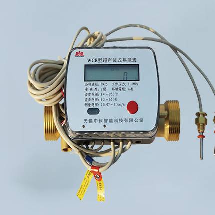
The heat meter consists of a calculator, a flow sensor and a temperature sensor (Figure 1):
五、

Figure 1
六、
Calculator (integrator): Used to receive signals from flow sensor and paired temperature sensor, and calculate, accumulate, store and display heat in heat exchange system.
Flow sensor (flowmeter): It is the most important component of the heat meter, and its performance directly reflects the overall performance, quality and grade of the heat meter. Its function is mainly to generate the flow signal of heat-carrying liquid in the heat exchange circuit, which is a function of volume or mass, or a function of volume flow or mass flow.
Temperature sensor (paired platinum resistor): Used in the heat exchange circuit to measure the temperature signals of the heat carrier liquid at the inlet and outlet at the same time.
| cal | DN15~40 |
| Maximum water reading(m³) | 999999.99 |
| Accuracy grade | Level 2 |
| pressure loss | <25kPa(Under common traffic) |
| Maximum working pressure | 1.6MPa |
| Heat consumption calculation | Starting from 0.25k |
| temperature range | 4℃ ~ 95℃ |
| Temperature difference range | 3℃ ~ 70℃ |
| Temperature resolution | 0.01℃ |
| ambient temperature | Class A 5℃ ~ 55℃ |
| Battery working time | 6 years (lithium battery) |
| Temperature sensor | PT1000 platinum resistor |
| Display digit | 8 |