


1. Purpose and scope of application
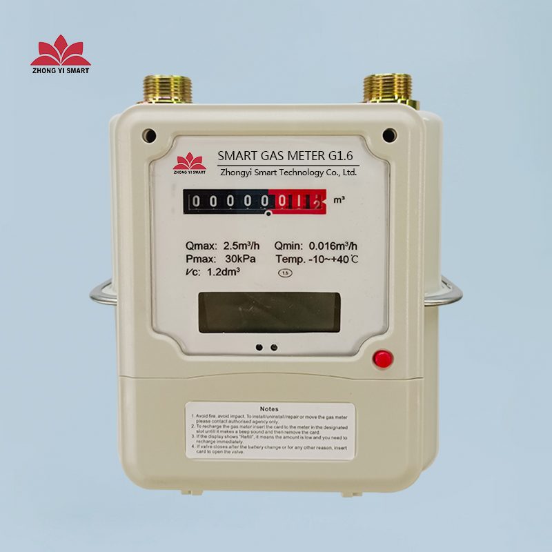
Membrane gas meter is a kind of flow measuring instrument, which is suitable for cumulative flow measurement of combustible gases such as gas, natural gas, liquefied petroleum gas and biogas in urban pipelines with a working pressure of 0.5~20kPa. A variety of different specifications can be widely used in urban residents' families.
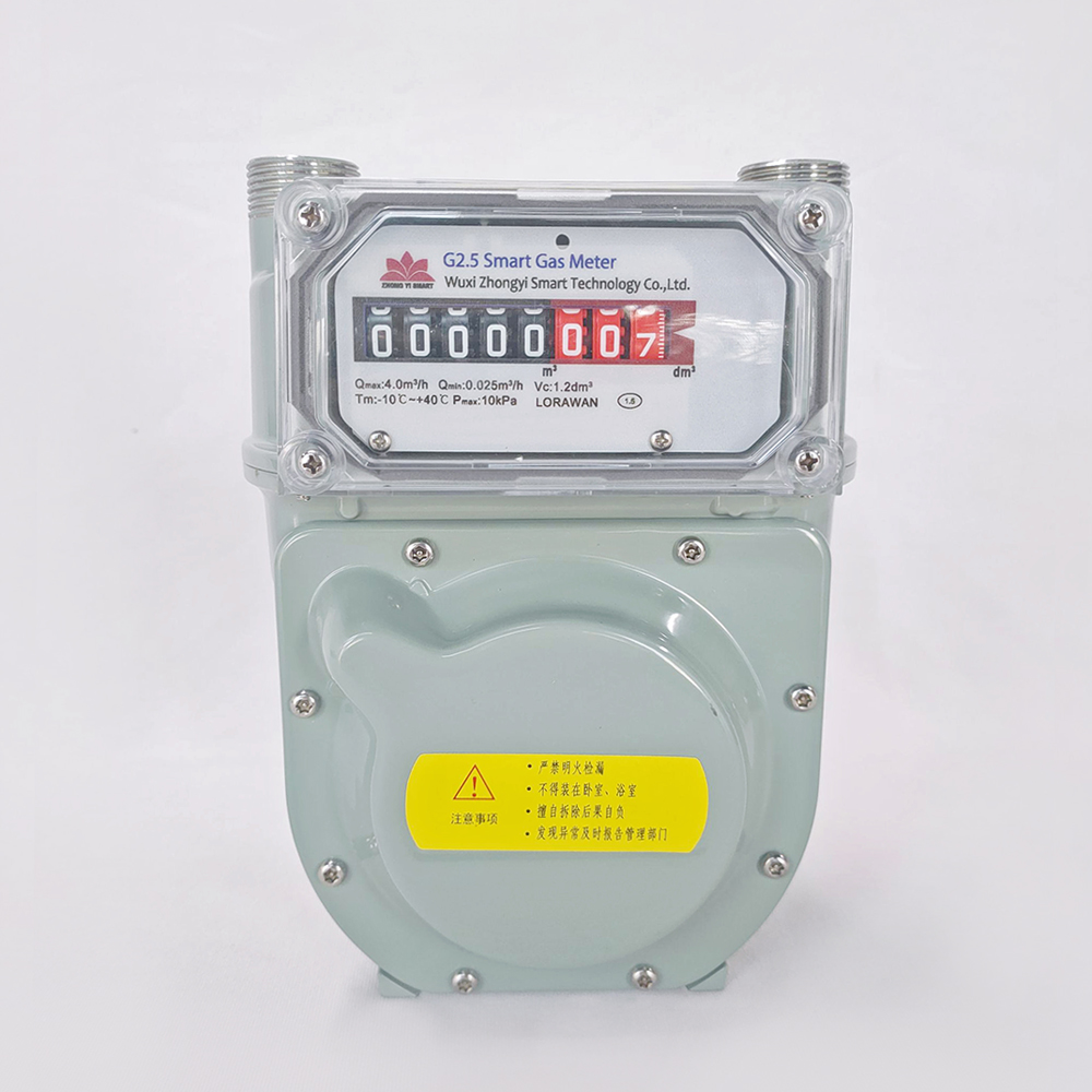
2.Main specifications and technical parameters
2.1. Product model and meaning

2.2. Specifications
1.6:2.5
2.3. Main technical indicators
|
Main Indicators |
Model Specifications |
||
|
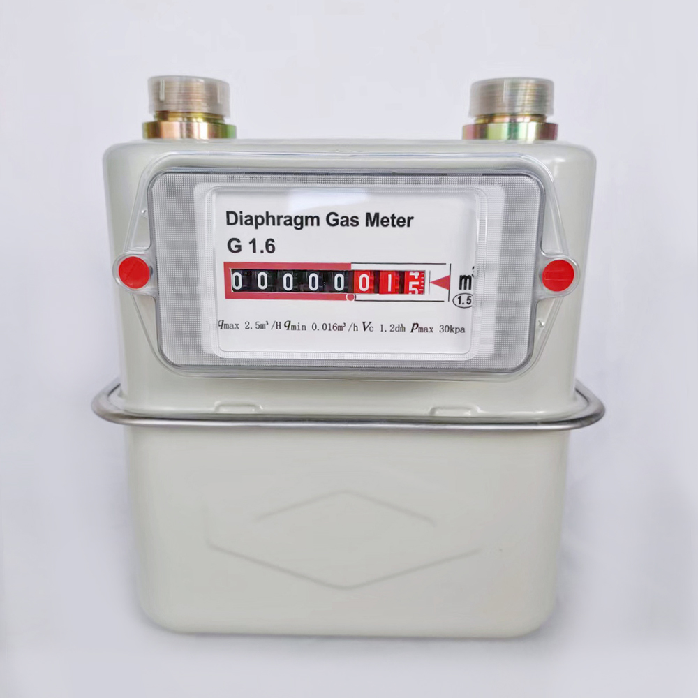
G1.6 |
G2.5 |
||
|
Nominal flow qn (m³/h) |
1.6 |
2.5 |
|
|
Maximum flow qmax (m³/h) |
2.5 |
4 |
|
|
Minimum flow qmin (m³/h) |
0.016 |
0.025 |
|
|
Level of accuracy |
Level 1.5 |
||
|
Working pressure (kPa) |
0.5—20 |
||
|
Basic error |
0.1qmax≤q≤qmax |
±1.5% |
|
|
qmin≤q<0.1qmax |
±3% |
||
|
Pressure loss(Pa) |
≤200 |
||
|
Joint center distance(mm) |
130 |
||
|
Connector thread |
M30×2 |
||
|
Maximum reading(m²) |
99999.999 |
||
|
Working temperature(℃) |
-10~+40 |
||
|
Weight (kg) |
1.7 |
||
2.4. The ambient temperature of the instrument: -10℃~+40℃
2.5. The overall dimensions are shown in the figure
2.6. Implementation Standards: GB/T6968-2011
3. Main structure and working principle
3.1. Structure
Diaphragm gas meter is made up of movement (lower casing), rotary valve, connecting rod, gear transmission mechanism, casing, counter. The key component movement is divided into four small chambers by two synthetic rubber membranes in the front and rear of the lower shell, which are used as the metering chamber for the gas flow. The rotary valve is composed of a valve cover and a valve seat, and has good flat sealing performance. The connecting rod gear transmission mechanism is composed of long connecting rod, short connecting rod, transmission wheel and other parts, which are used to drive the counter to rotate and control the rotation angle of the rotary valve. The shell is made of high-strength aluminum alloy and has good sealing performance.
3.2. Working principle
The working principle of the gas meter is that when the gas enters the meter from the inlet, the gas flow direction is distributed through the rotary valve, and the gas flows into the two metering chambers, pushing the film to discharge the gas from the other two metering chambers, and at the same time, the film is shaken by the rocker arm. The lever makes the pull arm swing and then drives the linkage mechanism, so that the rotary valve rotates. When the rotary valve turns to a certain angle position, the air intake of two of the metering chambers stops and turns to exhaust, and the other two metering chambers start to enter air, so that the cycle is continuous, and the gear is driven by the connecting rod mechanism to rotate and change speed, so that the word wheel type The indicating device indicates the flow value.
4. Installation and use
During transportation and storage, it should be kept in an upright state, and it should not be placed upside down, sideways, lying down, or subjected to severe impact, vibration and collision.
| Maximum flow qmax | 2.5 |
| Minimum flow qmin | 0.016 |
| Working pressure (kPa) | 0.5—50 |
| Level of accuracy | Level 1.5 |